Designation of the Sensor Slides and Sensors
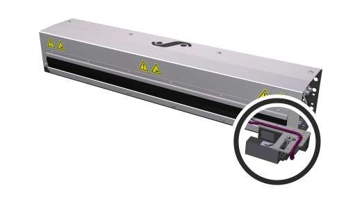
When establishing the cable connections, observe the correct allocation of the sensor slides of the sensor positioner to the connecting sockets on the web guiding controller.
According to the BST definition, the following allocation applies:
The sensor slide that is located on the left of the web in the web running direction (viewed from the top of the material) is sensor slide 1.
The top of the material is also the side of the web that has no direct contact with the deflection pulleys of the guiding device.
The following figures and tables specify the respective allocations for both possible web running directions.
Web running direction from the bottom to the top
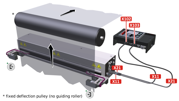
Sensor slides | Sensor positioner connecting plug | Connecting socket on the controller | Allocated | Key on the | Guiding mode | |
|---|---|---|---|---|---|---|
|
| X11 | X102 | Sensor 1 |
| Left web edge* |
|
| X21 | X103 | Sensor 2 |
| Right web edge* |
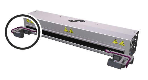
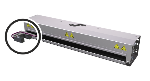

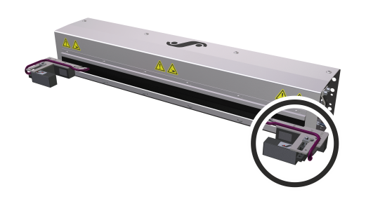

* in the web running direction
Web running direction from the top to the bottom
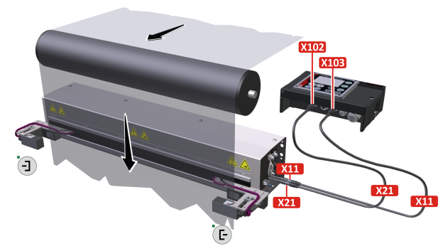
Sensor slides | Sensor positioner connecting plug | Connecting socket on the controller | Allocated | Key on the | Guiding mode | |
|---|---|---|---|---|---|---|
|
| X21 | X102 | Sensor 1 |
| Left web edge* |
|
| X11 | X103 | Sensor 2 |
| Right web edge* |
* in the web running direction
