Installation of a Line and Contrast Sensor
This chapter describes the installation of a BST line and contrast sensor (CLS Pro 600, CLS CAM 200) to the integrated sensor holder of the sensor slide.
Accessories required
Order Number | Designation |
|---|---|
249 805 | Mounting kit for line/contrast sensor |
Procedure
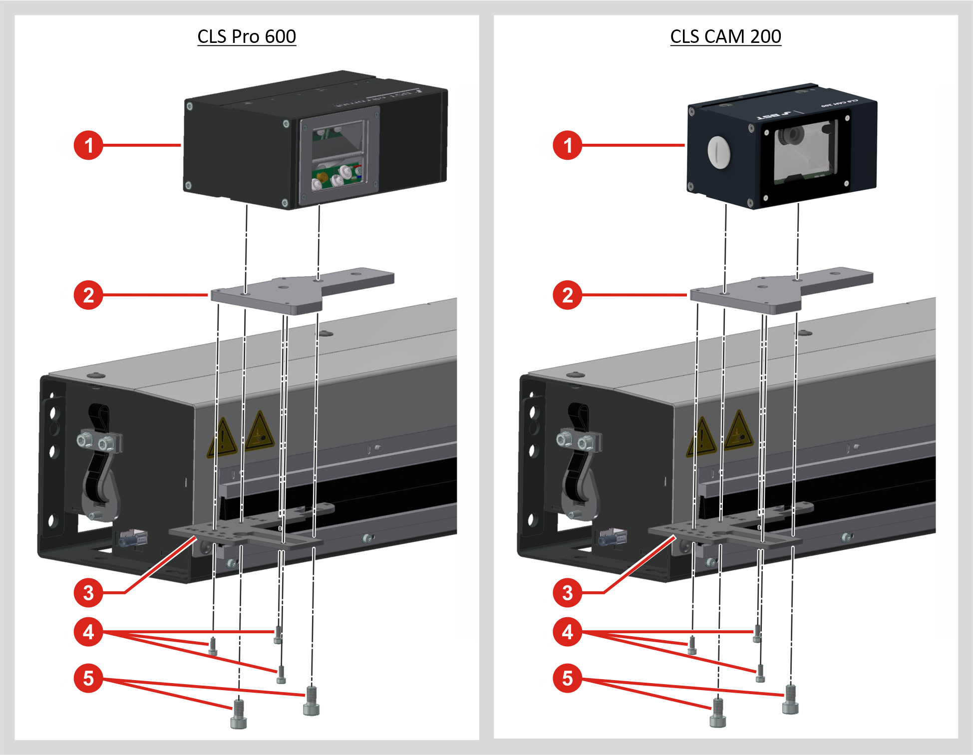
- Fix the adapter plate ② to the sensor holder ③ of the sensor slide using the three screws ④ (M3x8).
- Then fix the line and contrast sensor ① (CLS Pro 600, CLS CAM 200) to the adapter plate ② using the two screws ⑤ (M6x12).
