Link Between Oscillation Amplitude and Guiding Setpoint
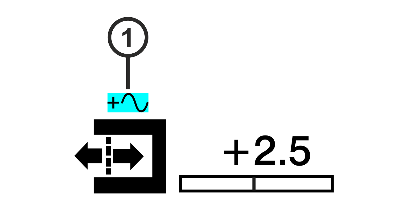
If the oscillation is switched on, the symbol ① ( ) appears above the sensor symbol for the display of the guiding setpoint in the operation display. It indicates that the current position of the web edge differs from the adjusted guiding setpoint (+2.5 in the example) due to the lateral displacement (oscillation).
For determining the current edge position an offset value must be added to the adjusted guiding setpoint.
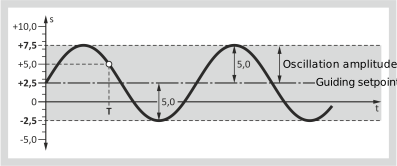
The example illustrated shows the deviation between the current web edge position and the adjusted guiding setpoint. At the moment T of the oscillation, the web edge is in position +5.0 although the display continues to show the value +2.5 for the guiding setpoint.
If the operating mode is changed from Automatic to Manual mode during the oscillation, the current web position is detected by the edge sensors and is saved in the controller. After reactivation of the Automatic mode, the oscillation continues from the edge position where it was stopped before.