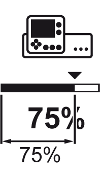
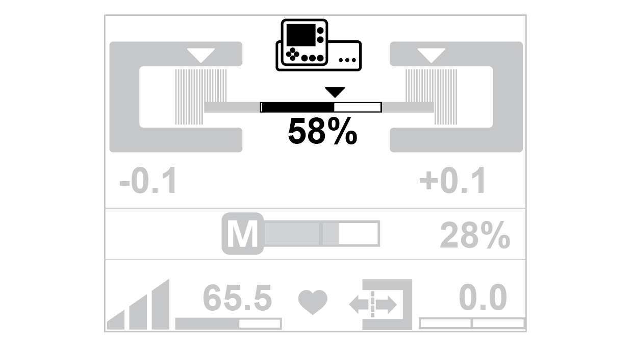
Line and Contrast Sensor Operation Display (Sensor 3)
The operation display for sensor 3 appears only if a CLS Pro 600 line and contrast sensor is connected to the controller.
The appearance of the operation display depends on the guiding mode that is selected on the line and contrast sensor.
Line guiding | Contrast guiding |
|---|---|
|
|
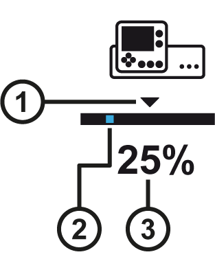
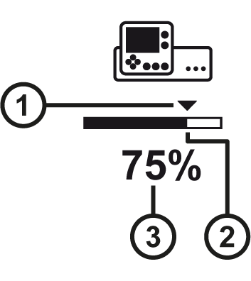
Symbol meanings
① | The triangle marks the guiding setpoint set. |
② | Line guiding: |
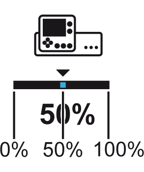
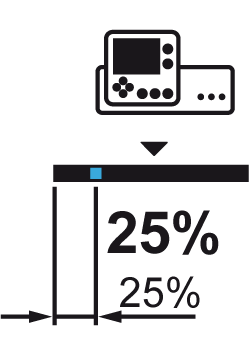
③ | The value specifies the relative position of the line or contrast transition in relation to the sensor scanning area. |
Display of the position of the line to be scanned (example)
Guiding setpoint = 50% | Guiding setpoint = 25% |
|---|---|
|
|
The line is located in the center of the sensor scanning area. | The line is located at 25% of the sensor scanning area. |
Display of the position of the contrast transition to be scanned (example)
Guiding setpoint = 50% | Guiding setpoint = 75% |
|---|---|
|
|
The contrast transition is located in the center of the sensor scanning area. | The contrast transition is located at 75% of the sensor scanning area. |