Displaying System Components
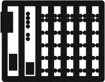
This service display indicates the system components that are connected to the controller.
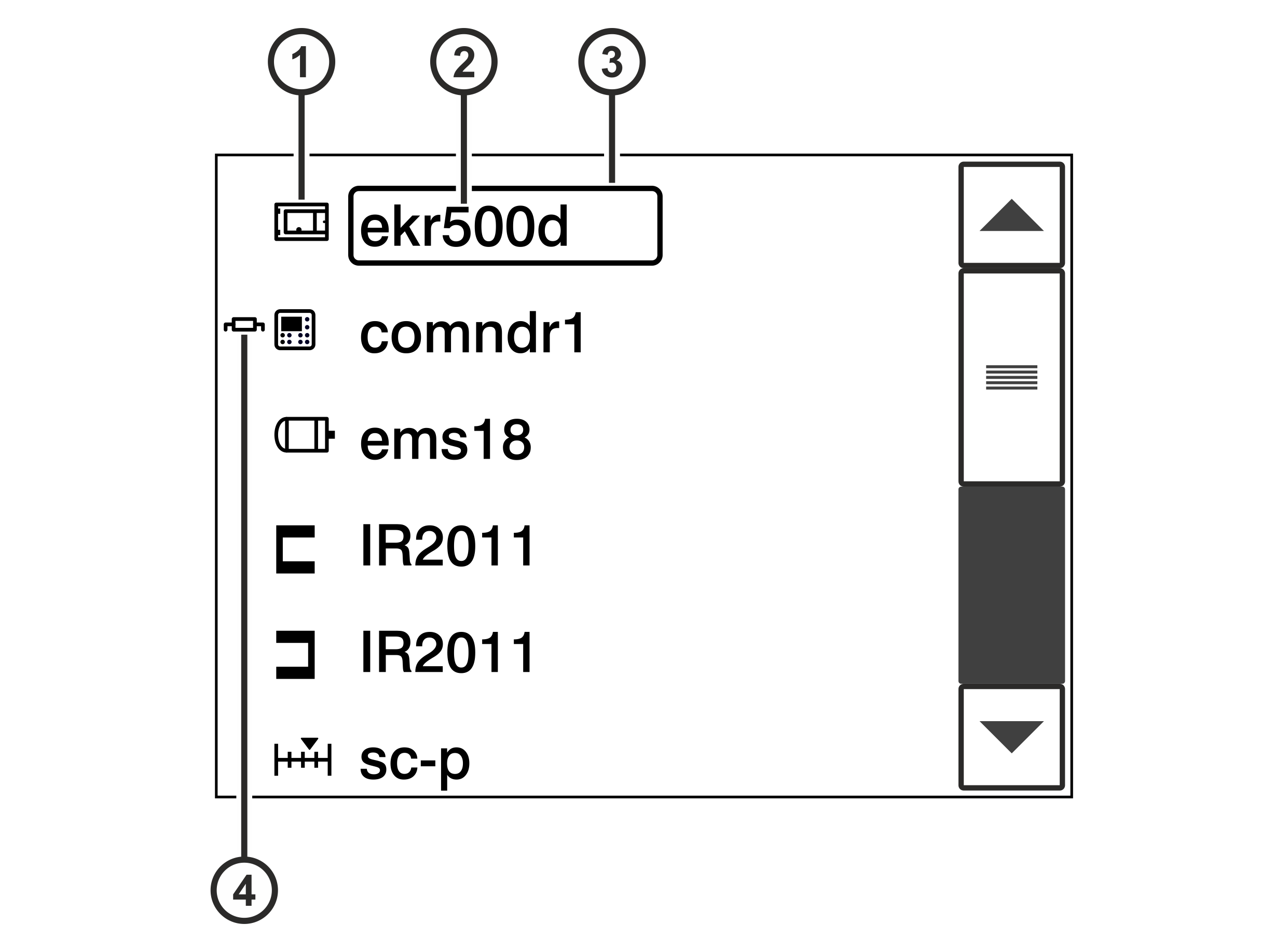
Pos. | Meaning |
|---|---|
① | Symbol of the system component |
② | Type designation of the system component |
③ | For system components, whose type designation is placed in a black frame, you can call up the Switch Position service display by tapping the frame on the touchscreen (see Displaying Switch Positions). |
④ | The internal terminating resistor of the system component is activated. |
The above illustration shows the system components of a standard web guiding system. The following table lists possible other system components.
Symbol | System component | Designation | Type |
|---|---|---|---|
| Controller | controller | |
| Control panel | comndr1 | ekr commander control panel of the controller |
comndr2 | Additional ekr commander control panel (remote control) | ||
| Edge sensor 1/2 | IR2011 | Optical sensor IR 2011 |
IR2012 | Optical sensor IR 2012 | ||
US2010 | Ultrasonic sensor US 2010 | ||
WideAr | Infrared wide array edge sensor IR SEN …, | ||
FvgPos | FVG POS 100 sensor positioner | ||
| CCD camera 1/2 | ccd 1, ccd 2 | CCDPro or CCD CAM 100 CCD camera |
| Line/contrast sensor (Sensor 3) | cls600 | CLS Pro 600 line and contrast sensor |
| Actuator | ems… | Electric motor powered actuator EMS… |
| Servo center transducer | sc-s | OMG 4, OMG 8, CK 37 servo center transducer |
sc-p | Actuator with position feedback | ||
| Positioning unit | fvgSp 1, fvgSP 2 | Positioning unit for Sensor 3 |
| C2E coupler | c2e | CAN-To-Ethernet coupler |
| External IO module | ext-IO |
|



Calling up the service display
- Activate the System components service display in the setup menu (see Calling up the Setup Menu).
- A list including all system components connected is displayed.
- Use the scroll bar on the right side to scroll the list up or down.
- Press the
 button at the end of the list to quit the service display.
- The setup menu is displayed.