You can specify user-defined warning and error limits for the width measurement using a special setting menu. If the material width measured falls below or exceeds the specified limits, this is shown in the display by a coloured signal field (see Displaying the Web Width).
Definition of the warning and error limits
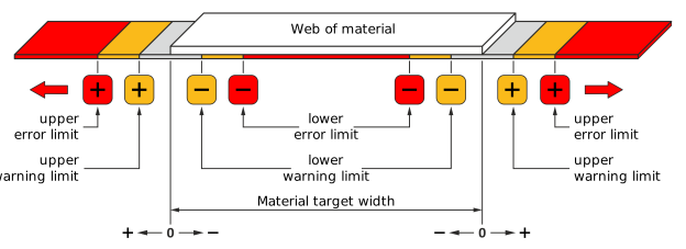
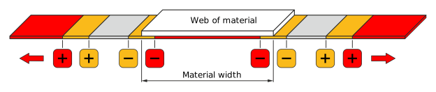
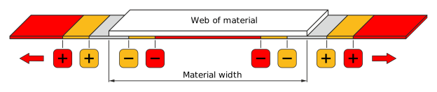
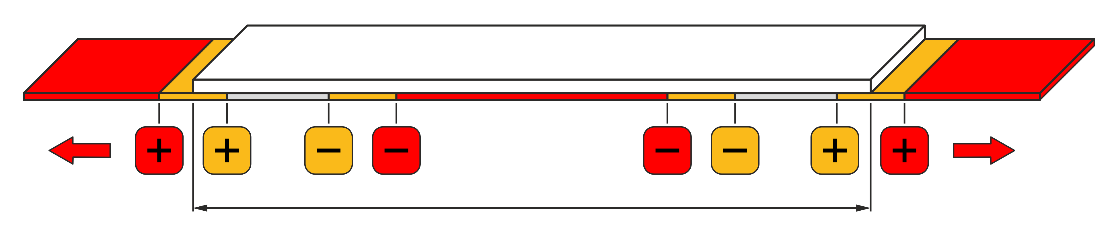
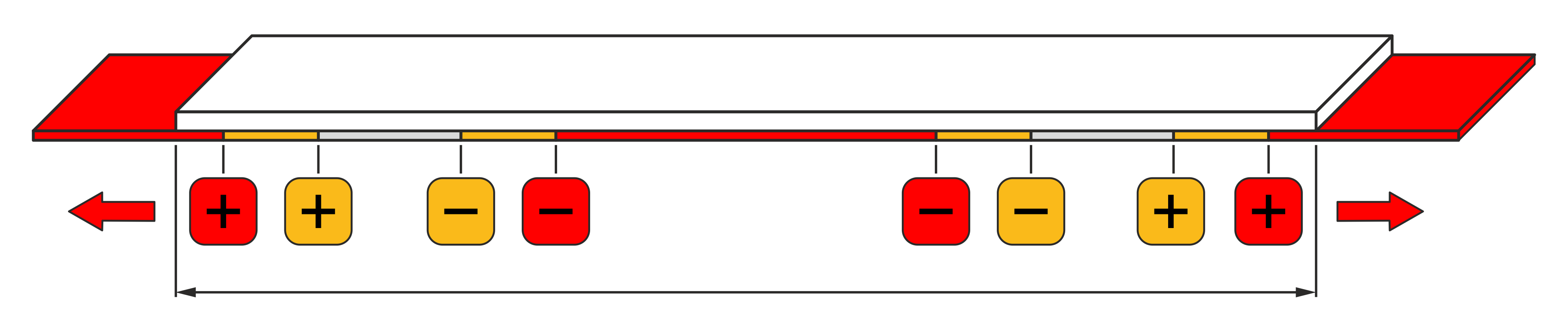
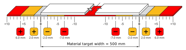
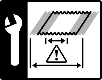
The following illustration shows the definition of the warning and error limits and the resulting tolerance (grey), warning (orange) and error (red) ranges.
Definition of the warning and error limits
The width measurement signals five states:
The web of material is much too small. The width measured is within the lower error range (24 V⎓ at output 3, terminal 28).
The web of material is too small. The width measured is within the lower warning range (24 V⎓ at output 2, terminal 27).
The material width is correct. The width measured is within the tolerance range.
The web of material is too wide. The width measured is within the upper warning range (24 V⎓ at output 2, terminal 27).
The web of material is much too wide. The width measured is within the upper error range (24 V⎓ at output 3, terminal 28).
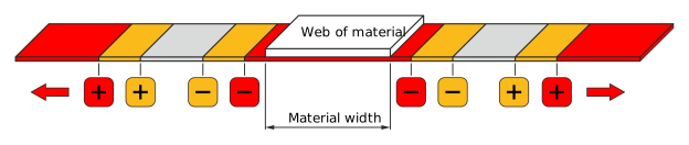
Example for the specification of the warning and error limits
Example for the specification of the warning and error limits
The following table shows the values for the target width and the warning and error limits set in the example.
Rotate the smartphone by 90 degrees to show the entire table.
Lower error limit
Lower warning limit
Target width
Upper warning limit
Upper error limit
The following tolerance, warning and error limits result from the values specified in the example:
Rotate the smartphone by 90 degrees to show the entire table.
Lower error range (red)
Lower warning range (orange)
Tolerance range (grey)
Upper warning range (orange)
Upper error range (red)
< 486 mm
486 … 496 mm
496 … 504 mm
504 … 512 mm
> 512 mm
Specifying and activating the warning and error limits
The warning and error limits for the width measurement are specified using a special setting menu. For the specified limits to be effective, they need to be activated.
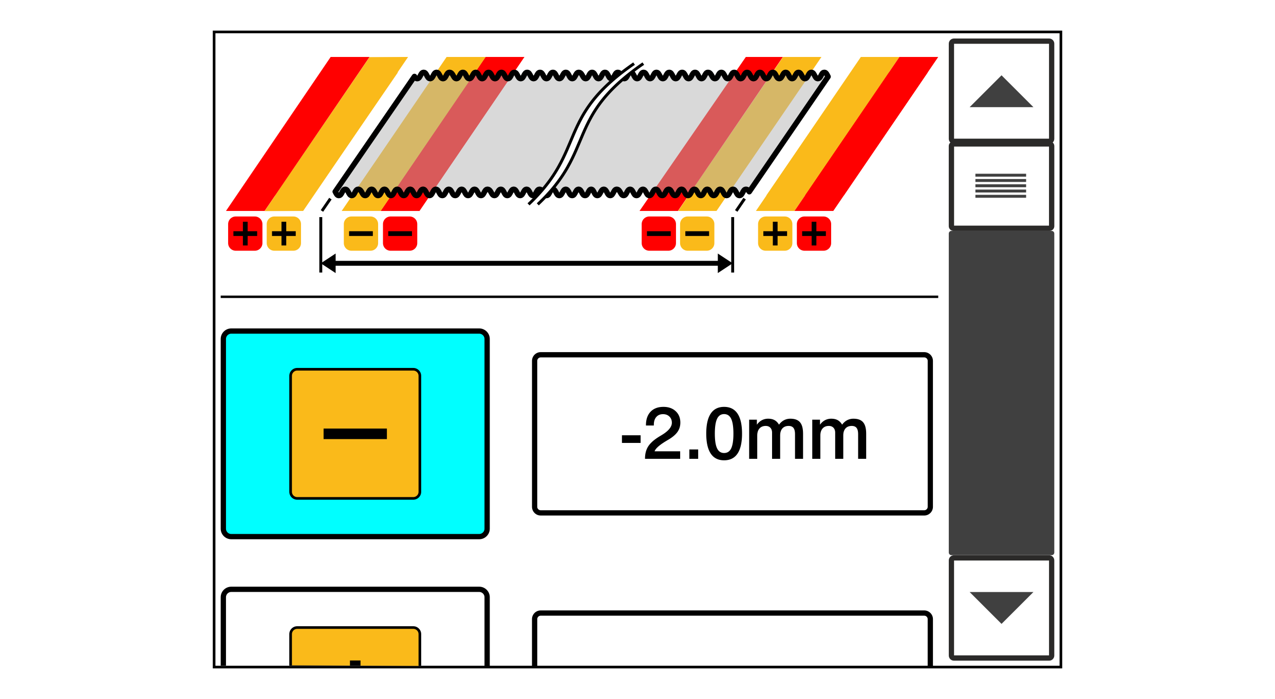
Setting menu for the warning and error limits
Call up the setting menu for the warning and error limits of the width measurement in the setup menu (see Calling up the Setup Menu).
The setting menu is displayed.
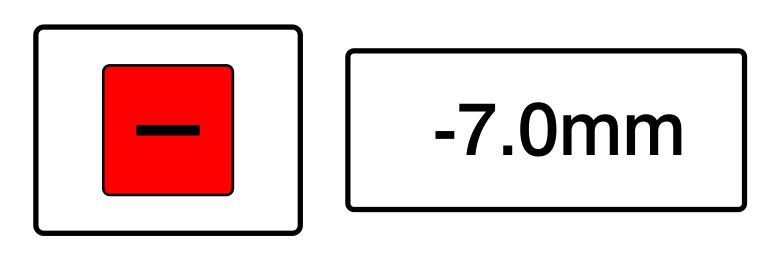
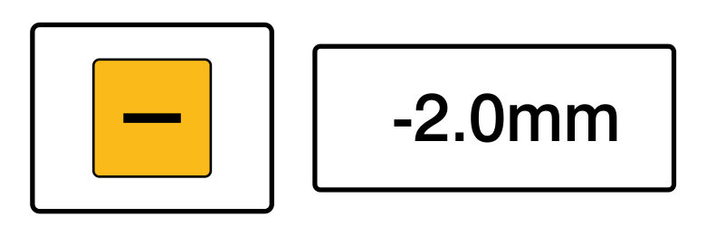
For specifying the warning and error limits tap on the editing field behind the corresponding Minus or Plus button.
A numeric keypad is displayed.
Enter the desired value for the warning or error limit.
Confirm your entry with the button.
The keypad is closed.
Switch the selected warning or error limit on by tapping on the corresponding Minus or Plus button.
If switched on, the button is displayed with a blue background.
Digital message outputs
The controller has digital message outputs for the warning und error limits. If the material width measured falls below or exceeds the specified limits, this is signaled by a 24 V⎓ signal at the corresponding digital output.
Requirement: The function table 9 for the digital inputs and outputs is selected. For selecting the function table see installation and commissioning manual ekr 500 digital Unit Touch, document number MD.497.
Rotate the smartphone by 90 degrees to show the entire table.
Function table 9
Output
Terminal
Width Measurement Message
2
27
Warning: Material width has fallen below or has exceeded the warning limit
3
28
Error: Material width has fallen below or has exceeded the error limit
 button.