Overview
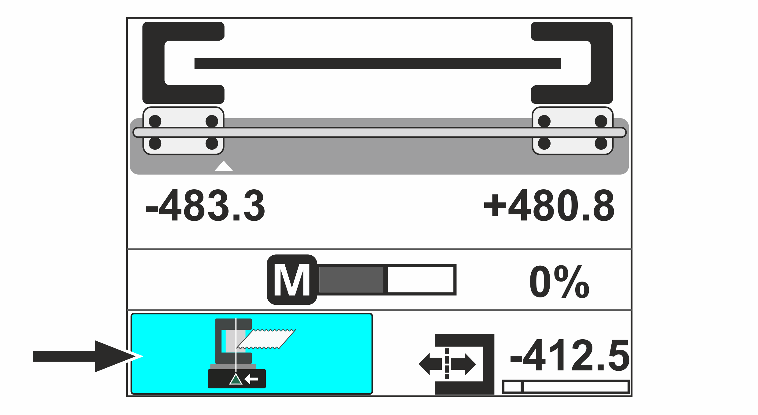
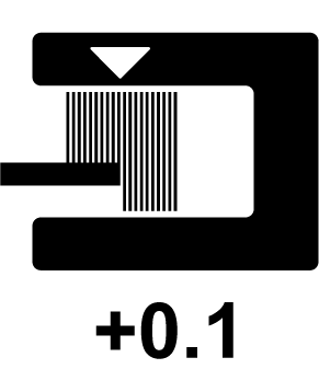
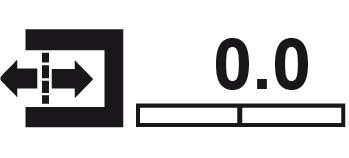
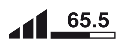
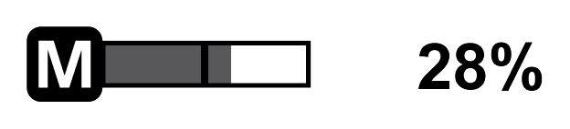
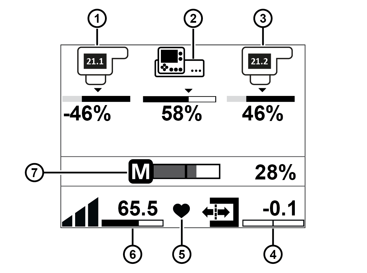
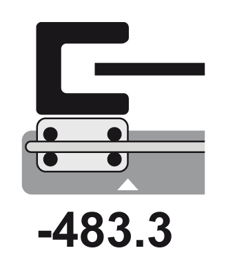
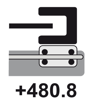
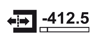
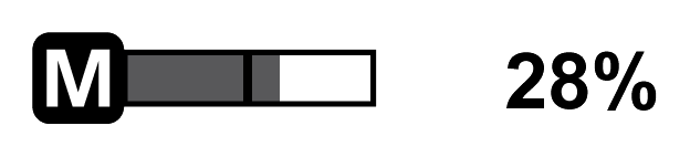
The operation display in the display of the control panel shows the different operating states and all relevant control parameters as graphical symbols and numeric values. You will find the meanings for the individual symbols in the following illustration.
Application with edge sensors
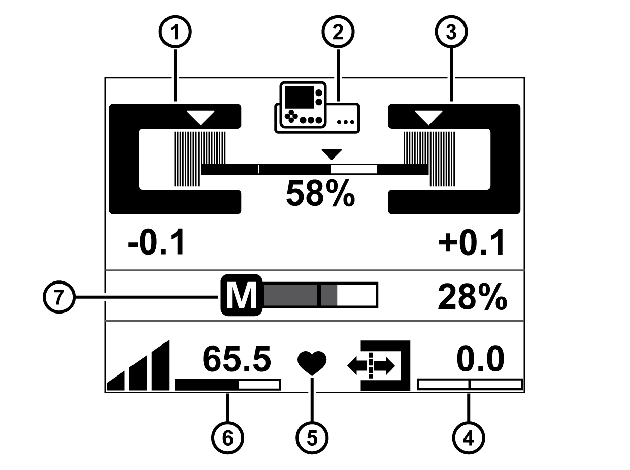
Pos. | Symbol | Display function |
|---|---|---|
① |
| Operation display edge sensor (Sensor 1) |
② |
| Operation display line / contrast sensor (Sensor 3) |
③ |
| Operation display edge sensor (Sensor 2) |
④ |
| Displays the setpoint of the web edge |
⑤ |
| Status display System OK (heart beats) |
⑥ |
| Displays the controller gain |
⑦ |
| Actuator operation display |
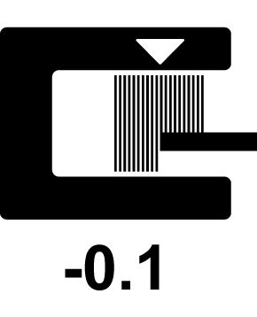
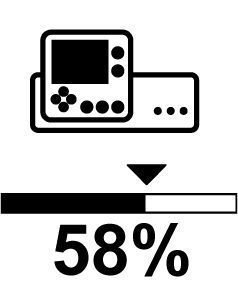

Application with CCD cameras
Pos. | Symbol | Display function |
|---|---|---|
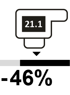
① |
| Operation display CCD camera (left edge) |
② |
| Operation display line / contrast sensor (Sensor 3) |
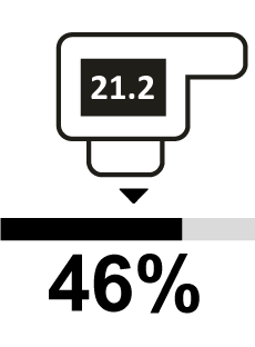
③ |
| Operation display CCD camera (right edge) |
④ |
| Displays the setpoint of the web edge |
⑤ |
| Status display System OK (heart beats) |
⑥ |
| Displays the controller gain |
⑦ |
| Actuator operation display |
Application with sensor positioner
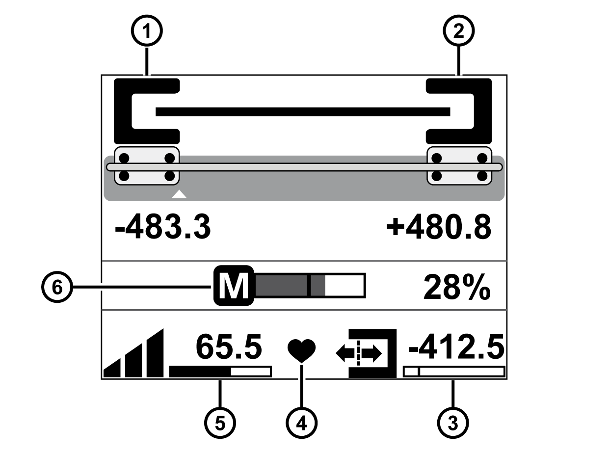
Pos. | Symbol | Display function |
|---|---|---|
① |
| Operation display edge sensor (Sensor 1) |
② |
| Operation display edge sensor (Sensor 2) |
③ |
| Displays the setpoint of the web edge |
④ |
| Status display System OK (heart beats) |
⑤ |
| Displays the controller gain |
⑥ |
| Actuator operation display |
If the function Automatic setpoint acceptance is activated, the display of the controller gain in the bottom left corner of the operation display is cross-faded by an additional button. To activate the function, see Automatic Setpoint Acceptance.