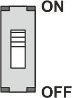
Using sliding switch S3 on the processor board, switch the internal terminating resistor for the connector socket X101 on or off depending on the application.
Sliding switch S3 on the processor board
Rotate the smartphone by 90 degrees to show the entire table.
Application
Switch S3
Function
Operation of the controller without other bus participants
ON
Internal terminating resistor is switched on (default factory setting)
Operation of the controller with other bus participants
OFF
Internal terminating resistor is switched off
Other bus participants that can be connected up to the ekr CON 600, ekr CON 600 net controller are, for example:
Drive Module 160 (external output stage for actuator EMS 23)
CLS Pro 600 line and contrast sensor
CLS CAM 100 object sensor
Additional ekr commander control panel (remote control)
BTL5 linear position sensor
The procedure for setting the internal terminating resistors of the other bus participants can be obtained from the separate operating instructions of the devices connected.
Setting the terminating resistor
NOTICE
Damage to the components from working on live parts.
▶Before opening the controller, switch off the power supply.
Electrically isolate the controller.
Open the controller’s housing cover.
Check the setting of the sliding switch S3 on the processor board.
If necessary, change the position of the sliding switch S3.