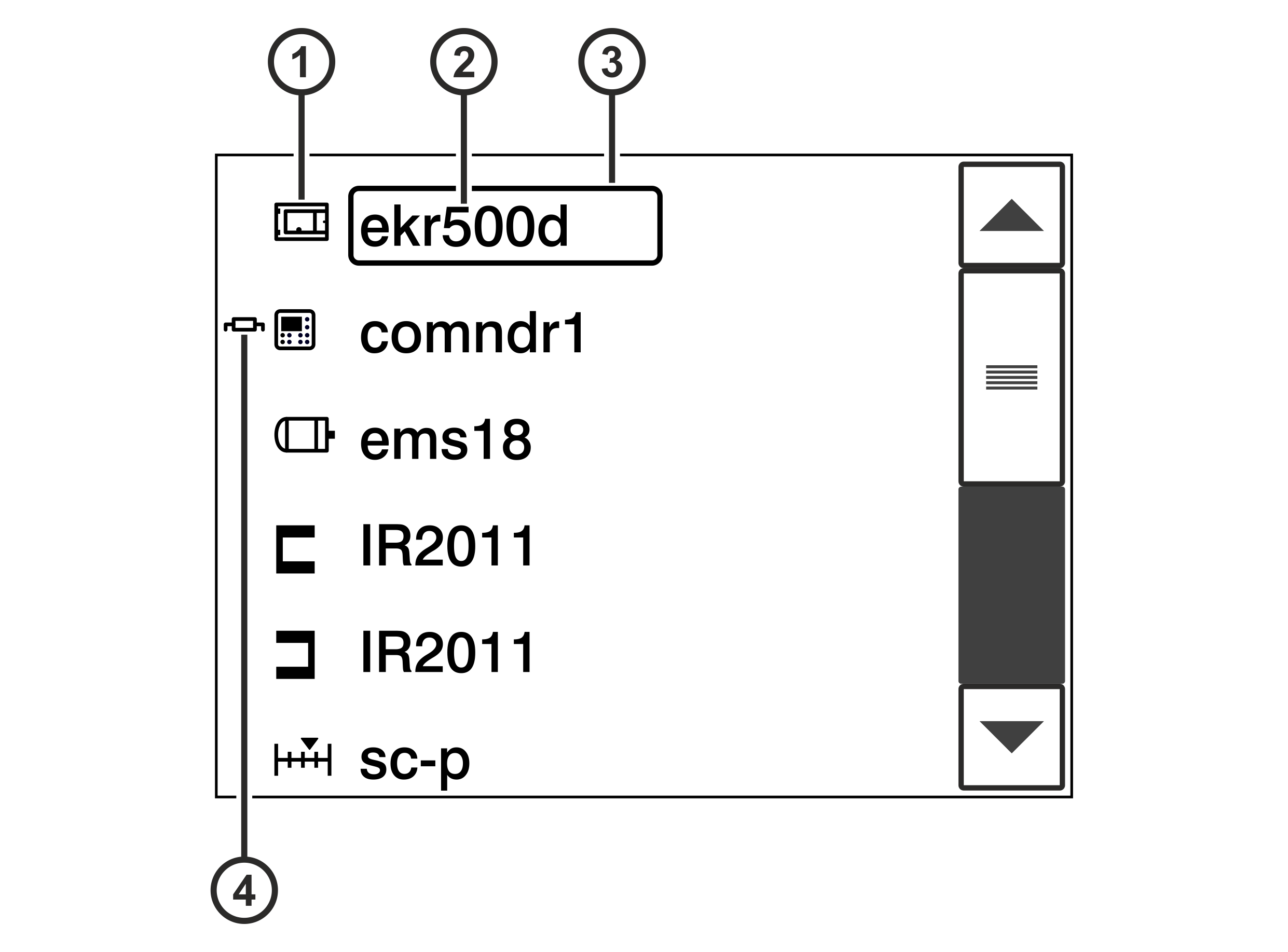
This service display indicates the system components that are connected to the controller.
Display of the system components connected (example)
Pos.
Meaning
①
Symbol of the system component
②
Type designation of the system component
③
For system components, whose type designation is placed in a black frame, you can call up the Switch Position service display by tapping the frame on the touchscreen (see Displaying Switch Positions).
④
The internal terminating resistor of the system component is activated.
The above illustration shows the system components of a standard web guiding system. The following table lists possible other system components.
Rotate the smartphone by 90 degrees to show the entire table.
Symbol
System component
Designation
Type
Controller
ekr500d
ekr 500 digital Unit Touch controller
Control panel
comndr1
ekr commander control panel of the controller
comndr2
Additional ekr commander control panel (remote control)
Edge sensor 1/2
IR2011
Optical sensor IR 2011
IR2012
Optical sensor IR 2012
US2010
Ultrasonic sensor US 2010
WideAr
Infrared wide array edge sensor IR SEN …, Ultrasonic wide array edge sensor US SEN …
FvgPos
FVG POS 100 sensor positioner
CCD camera 1/2
ccd 1, ccd 2
CCDPro or CCD CAM 100 CCD camera
Line/contrast/object sensor (Sensor 3)
cls600
CLS Pro 600 line and contrast sensor
cls100
CLS CAM 100 object sensor
Actuator
ems…
Electric motor powered actuator EMS…
Servo center transducer
sc-s
OMG 4, OMG 8, CK 37 servo center transducer
sc-p
Actuator with position feedback
Positioning unit
fvgSp 1, fvgSP 2
Positioning unit for Sensor 3
C2E coupler
c2e
CAN-To-Ethernet coupler
External IO module
ext-IO
Calling up the service display
Activate the System components service display in the setup menu (see Calling up the Setup Menu).
A list including all system components connected is displayed.
Use the scroll bar on the right side to scroll the list up or down.
Press the button at the end of the list to quit the service display.







 button at the end of the list to quit the service display.