Displaying the Web Width
You can show the web width measured in the display of the ekr commander control panel.
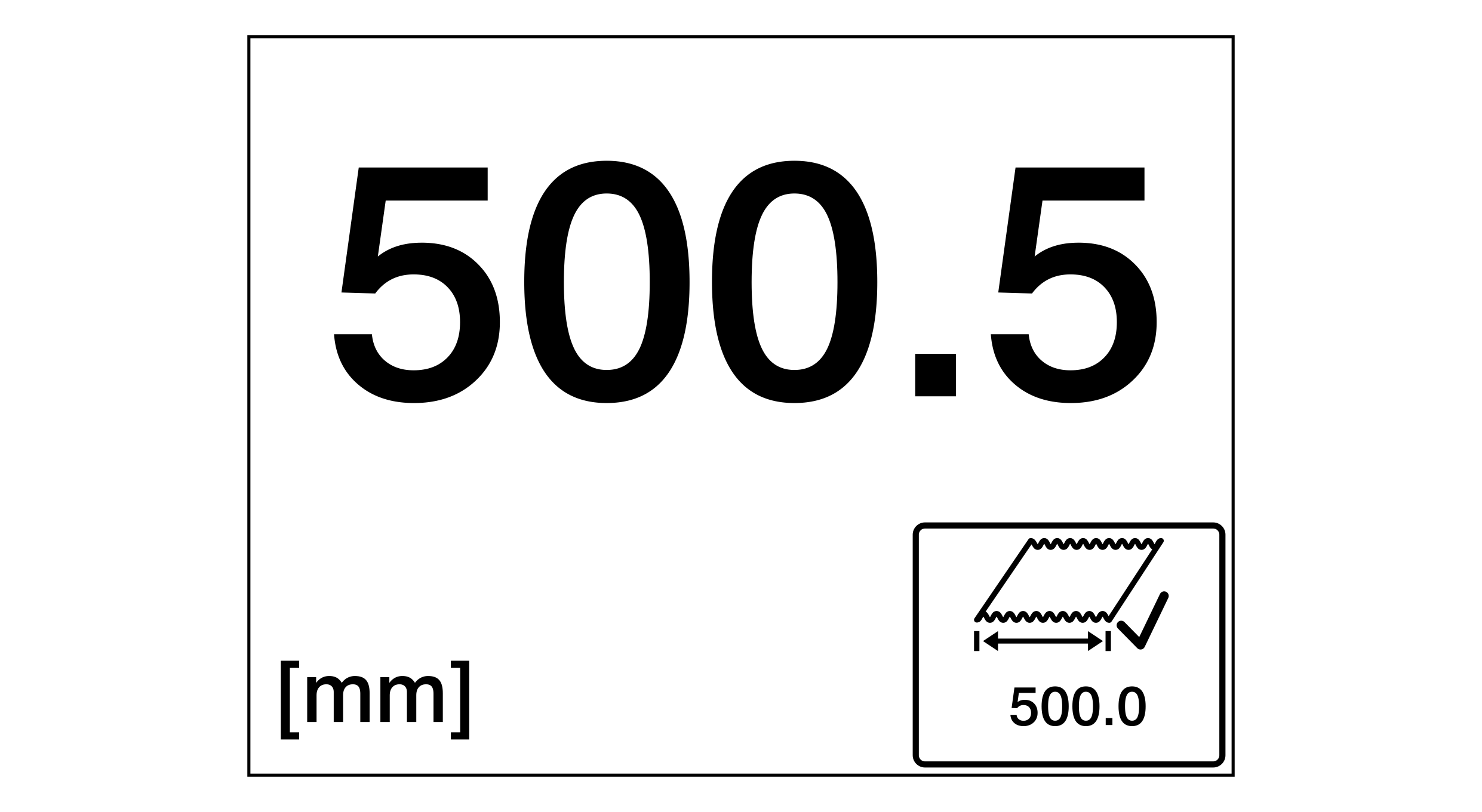
- Two edge sensors or one or two CCD cameras are connected to the controller.
- The material web is drawn in and the web edges are located in the measuring range of the edge sensors or CCD camera(s).
- The width measurement has been calibrated (see Calibrating the Web Width Measurement).
- The display of the web width is activated in the setup menu for the configurable displays and setting menus (see Switching the Configurable Displays and Setting Menus On/Off).
- The display shows the operation display.
- ▶Call up the display of the web width using the swiping function (see Configurable Displays and Setting Menus).
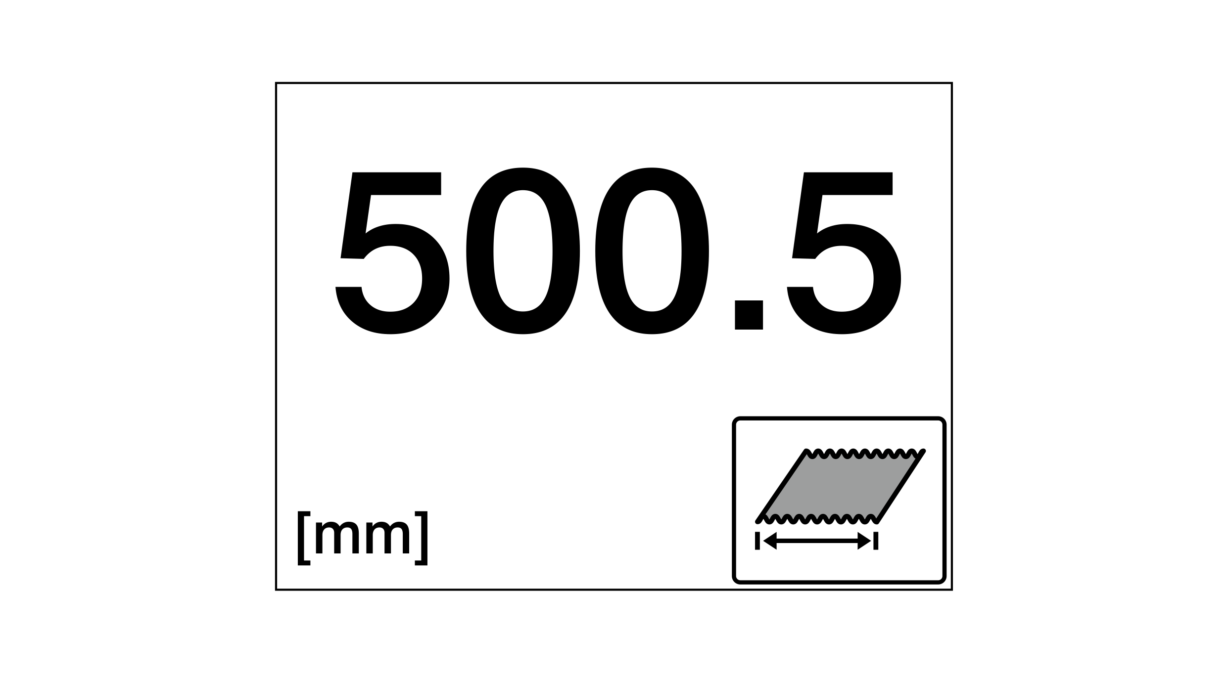
- The width of the material web determined by the web width measurement is shown in the display (500.5 mm in the example).
The display of the control panel shows five different states.
Display Screen | Meaning |
|---|---|
| No warning or error limit is activated. |
| The material width is within the tolerance range. |
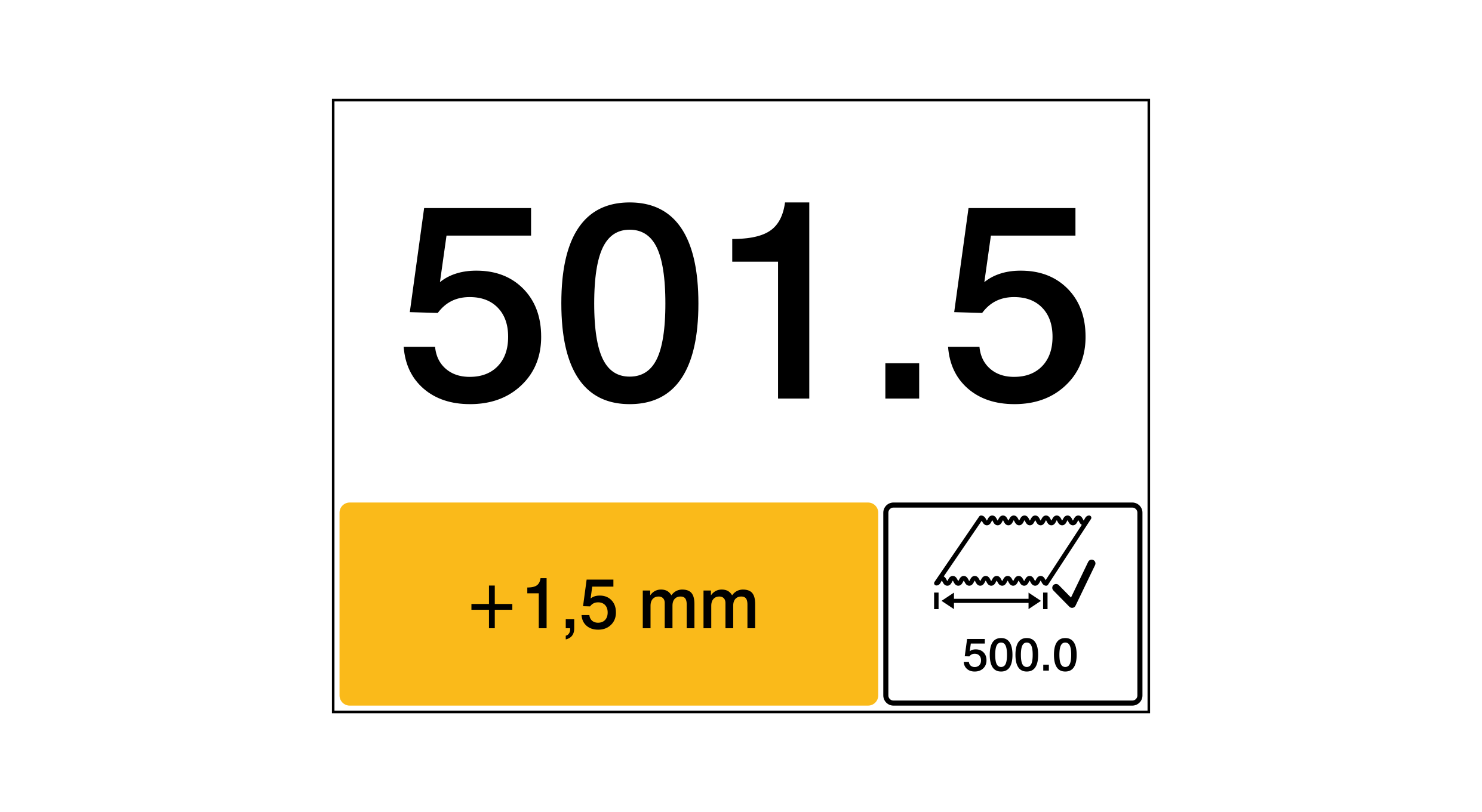
| The material width has fallen below the specified warning limit or has exceeded the specified warning limit. An orange signal field appears in the lower left corner of the display. The signal field shows the deviation of the material width measured with regard to the specified target width (+1.5 mm in the example). |
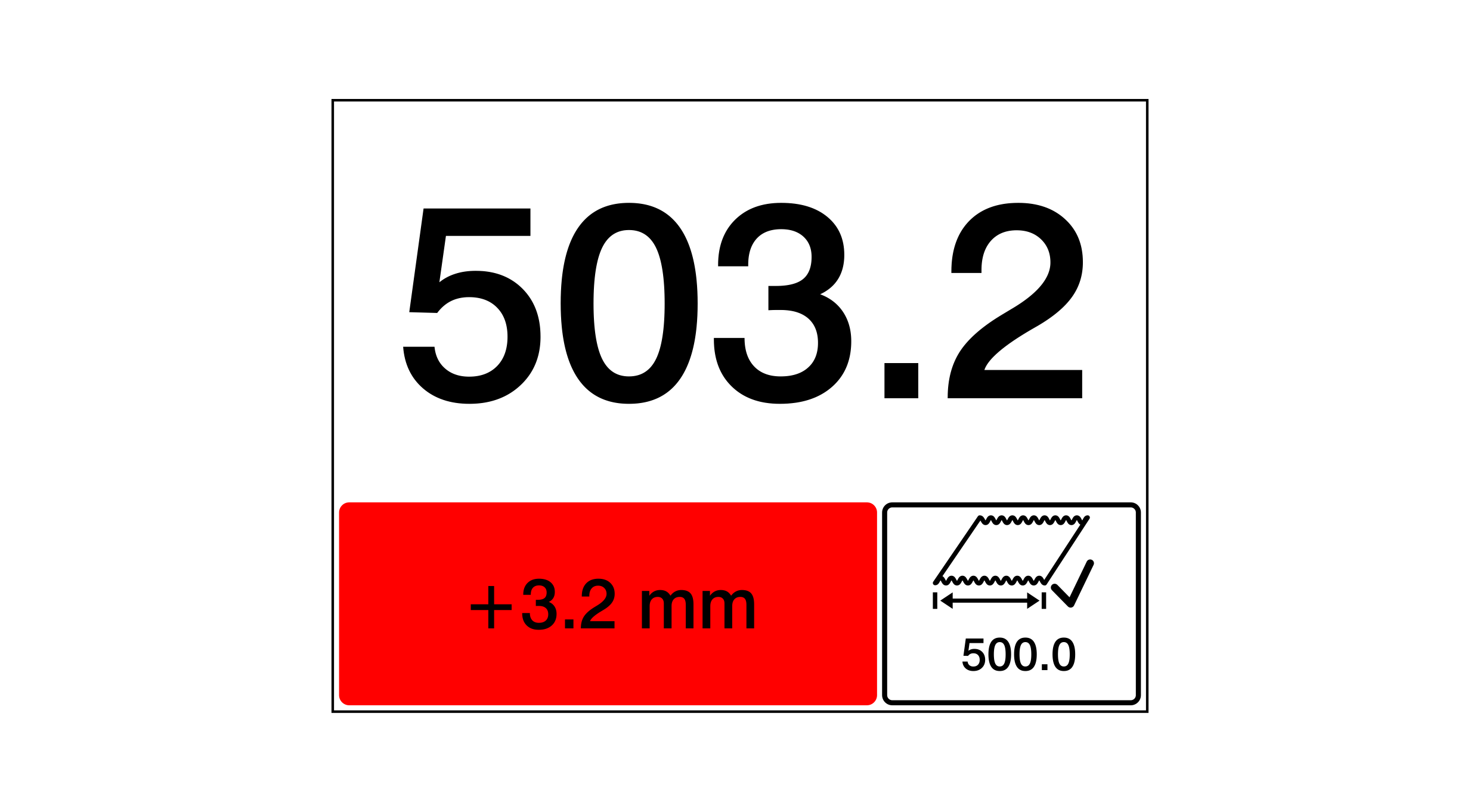
| The material width has fallen below the specified error limit or has exceeded the specified error limit. An red signal field appears in the lower left corner of the display. The signal field shows the deviation of the material width measured with regard to the specified target width (+3.2 mm in the example). |
| The material width could not be determined. Possible causes:
|
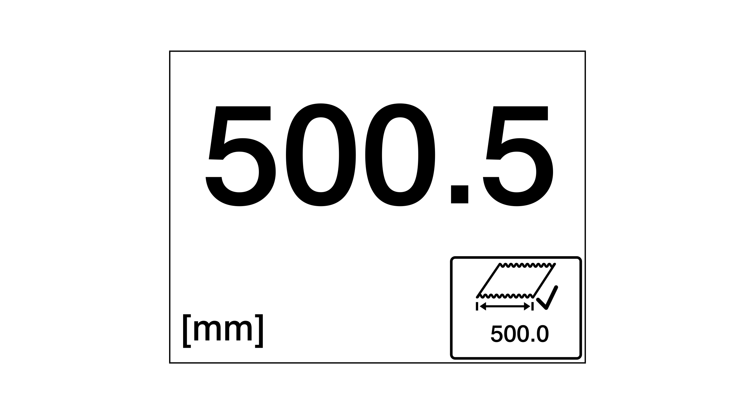

For specifying the warning and error limits see Specifying the Warning and Error Limits.