Connection Assignment
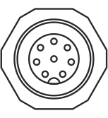
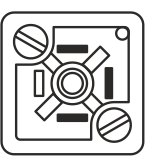
Designation | Socket | Function | Note |
|---|---|---|---|
X60 |
| Connection actuator | Leads internally to terminal strip X7 |
X70 |
| Connection power supply 24 V⎓ | Leads internally to terminal strip X6 |
X100 (internal CAN bus) |
| Connection SMART COM 100 control panel | Leads internally to terminal strip X9 |
X101 (internal/external |
| Connection Drive Module 160 | Leads internally to terminal strip X9 CAN bus configuration: |
Connection electric motor powered actuator EMS DRV 400 | |||
Connection line and contrast sensor CLS Pro 600, CLS CAM 200 (Sensor 3)* | |||
Connection object sensor CLS CAM 100 | |||
Connection additional SMART COM 100 control panel | |||
Connection BTL5 linear position sensor | |||
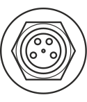
X102 (internal CAN bus) |
| Connection Sensor 1 (CAN bus) Notice: It is absolutely necessary that Sensor 1 is connected to socket X102. | Leads internally to terminal strip X8 |
X103 (internal CAN bus) |
| Connection Sensor 2 (CAN bus) Notice: It is absolutely necessary that Sensor 2 is connected to socket X103. | Leads internally to terminal strip X8 |
X104 (internal CAN bus) |
| CAN bus extension Notice: The connector socket X104 is only available with the standard version of the controller (ekr CON 610). | Leads internally to terminal strip X12 |
* An optionally available CAN bus distributor may be required for the simultaneous connection of several bus participants to the controller (see separate operating instructions of the components to be connected).
- ▶Before adding or removing system components on the connector sockets, electrically isolate the controller.
