Troubleshooting

- ▶Only allow qualified personnel instructed by BST service staff or authorized personnel to rectify malfunctions.
- ▶Only rectify malfunctions using the following measures or follow the instructions of BST customer service.
- ▶Observe all safety instructions in the chapter Maintenance and cleaning, see Maintenance and Cleaning.
Typical faults with their possible causes and measures for elimination are specified in the following.
- ▶For further information, please contact BST Customer Services, address see Customer Services.
|
Fault | |
|---|---|
|
Possible causes |
Measures for eliminating the fault |
The actuator / the guiding device trembles. | |
|---|---|
Guiding system overdrive. |
|
The actuator / the guiding device reacts too slowly or the guiding operates incorrectly. | |
|---|---|
The controller gain has been set too low. |
|
The actuator / the guiding device does not carry out any guiding movement. | |
|---|---|
An incorrect actuator has been selected during commissioning. |
|
The controller gain has been set too low. |
|
In operating mode Automatic the actuator / the guiding device moves to an end position and remains stationary there (with material web threaded in). | |
|---|---|
A material setup was not run after the material was changed. |
|
The actuator guiding direction is incorrectly set. |
|
In operating mode Center positioning the actuator / the guiding device moves to an end position and remains stationary there. | |
|---|---|
The actuator guiding direction is incorrectly set. |
|
The servo center transducer used (OMG 4, OMG 8, CK 37) has been installed incorrectly. |
|
| The actuator / the guiding device does not carry out any guiding movement. | |
|---|---|---|
The guiding device has moved into an end position or is blocking the electric motor powered actuator. |
| |
The guiding device moves with difficulty. |
| |
The material setup for the connected sensors has been carried out incorrectly. |
| |
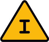
| An actuator with position feedback does not carry out any guiding movement. The symbol Limit switch active is shown in the display. | |
|---|---|---|
The actuator has reached a software limit switch. Driving the actuator in the corresponding direction is prevented. |
| |

| The actuator / the guiding device does not carry out any guiding movement. | |
|---|---|---|
The controller interlock is active. |
| |

| The actuator / the guiding device does not carry out any guiding movement. | |
|---|---|---|
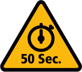
The actuator has been activated uninterrupted in the same direction for more than 50 seconds. |
| |
No material web has been threaded in. |
| |
There is no web tension present. |
| |
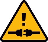
| The actuator / the guiding device does not carry out any guiding movement. | |
|---|---|---|
Fault in the bus connection between the controller and actuator. |
| |
| The EMS 23 actuator does not carry out any guiding movement. The warning symbol External motor output stage fault is shown in the display. | |
|---|---|---|
The hardware power monitoring of the external motor output stage Drive Module 160 has detected a fault (e.g. overload). |
| |
The external motor output stage Drive Module 160 is defective. |
| |

|
The actuator / the guiding device has moved to an end position and the motor switch off does not function. The LEDs of keys | |
|---|---|
|
As a result of the increased power consumption of the actuator, the supply voltage (24 V⎓) falls below the permissible voltage range. |
|
 or
or  on the control panel and the screen display flash.
The center position of the guiding device is not approached correctly. | |
|---|---|
When using an actuator with position feedback the servo centre transducer (OMG 4, OMG 8, CK 37) has inadvertently been selected during commissioning. |
|
All the settings for actuator, sensors, servo center transducer, etc. are correct, but the unit does not control. | |
|---|---|
The controller gain was inadvertently reduced to the minimum value (0.2). No guiding takes place in Automatic operating mode. |
|
A connected edge sensor is not working. | |
|---|---|
During commissioning, the incorrect settings have been met for the edge sensor connected. |
|
| An exclamation mark is shown in the sensor symbol of a digital edge sensor in the display. | |
|---|---|---|
Malfunctions have occurred several times in the communication between the controller and a digital edge sensor. |
| |

Web edge guiding with Sensor 1 ( | |
|---|---|
The respective sensor (Sensor 1 or Sensor 2) was not activated during commissioning. |
|
 ) or Sensor 2 (
 ) cannot be switched on.
| The warning symbol Supply voltage is shown in the display. | |
|---|---|---|
The supply voltage of the controller is outside the permissible range. |
| |

| The controller does not react to any operation. | |
|---|---|---|
The keyboard interlock is active. |
| |
| If the SETUP button is pressed, the SETUP key symbol with a padlock is displayed. | |
|---|---|---|
The setup lock is active. |
| |
A shifting of the guiding setpoint of the web using the arrow keys on the control panel is not possible. | |
|---|---|
The optional electronic remote precision adjustment EFE 1 is connected to the controller. |
|
| The controller does not react to any operation. | |
|---|---|---|
Fault in the bus connection between the controller and control panel. |
| |
The device address of the controller or the control panel has not been set correctly. |
| |
The internal terminating resistor in the controller and in the control panel is not set correctly. |
| |
The controller does not respond to any operation. | |
|---|---|
A remote control has been connected to the controller. The keys on the control panel are locked. |
|
The device address of the controller or the control panel has not been set correctly. |
|
The controller cannot be switched via the remote control function. | |
|---|---|
The remote control function is deactivated. |
|
|
Undefined behaviour of the controller. | |
|---|---|
|
The length of the connecting cable between the controller and the control panel is more than 20 m. |
|
|
The controller or the control panel has been mounted in the immediate vicinity of high-voltage components or lines. |
|
| During line and contrast scanning using the CLS Pro 600 line and contrast sensor an exclamation mark is displayed behind the symbol for Sensor 3. | |
|---|---|---|
The printed line / contrast transition to be scanned is not detected by the line and contrast sensor. |
| |
The printed line / contrast transition to be scanned is located outside the scanning area of the CLS Pro 600 line and contrast sensor. |
| |
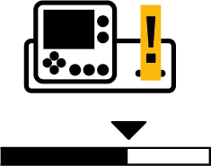
| During line, contrast or feature scanning using the CLS CAM 100 object sensor an exclamation mark is permanently displayed behind the symbol for Sensor 3. | |
|---|---|---|
The guiding criterion to be scanned (printed line, contrast transition or print feature) is not detected by the object sensor. |
| |
The guiding criterion to be scanned (printed line, contrast transition or print feature) is located outside the scanning area of the CLS CAM 100 object sensor. |
| |
When scanning a print feature, the web does not move or moves very slowly. |
| |
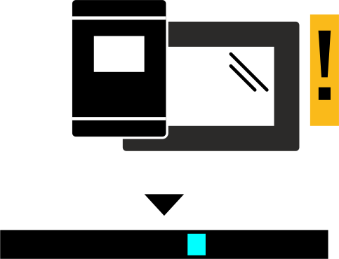
| With the web edge or the web center-line guiding with CCD camera, an exclamation mark is shown in the display behind the symbol of the CCD camera. | |
|---|---|---|
The web edge to be scanned is not detected by the CCD camera. | ||
The web edge to be scanned is located outside the measuring range of the CCD camera. | ||