This chapter describes the procedure for determining the distance of the end positions using the example of a web guiding system with pivoting frame guiding (DF).
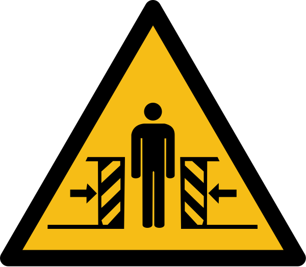
WARNING
Danger of death from actuator movements!
During function tests, parts of your body may be crushed, cut or hit.
▶Make sure that no persons remain in the vicinity of the pivot / traversing area of machine components that are positioned by the actuator.
Keep the left arrow key pressed until the actuator has reached its left end position.
The warning symbol Left limit switch active appears in the actuator operation display.
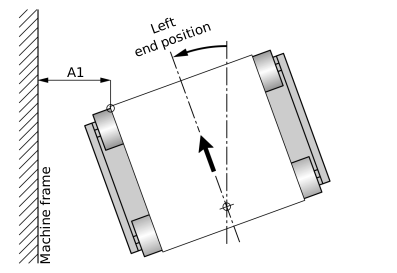
Guiding device in left end position
Measure the distance A1 of the left web edge at the outfeed roller of the guiding device to a fixed reference point (e.g. machine frame) and note it down.
Keep the right arrow key pressed until the actuator has reached its right end position.
The warning symbol Right limit switch active appears in the actuator operation display.
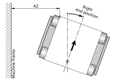
Guiding device in right end position
Measure the distance A2 of the left web edge at the outfeed roller of the guiding device to the reference point and note it down.
Calculate the distance of the end positions as follows:
End position distance = A2 – A1
Enter the determined distance of the end positions in the corresponding input field in the Actuator setup menu (see Activating the Normalized Display).