Calling up the Setup Menu
In the setup menu, activate the different setting functions and service displays of the controller. The setup menu comprises several pages.
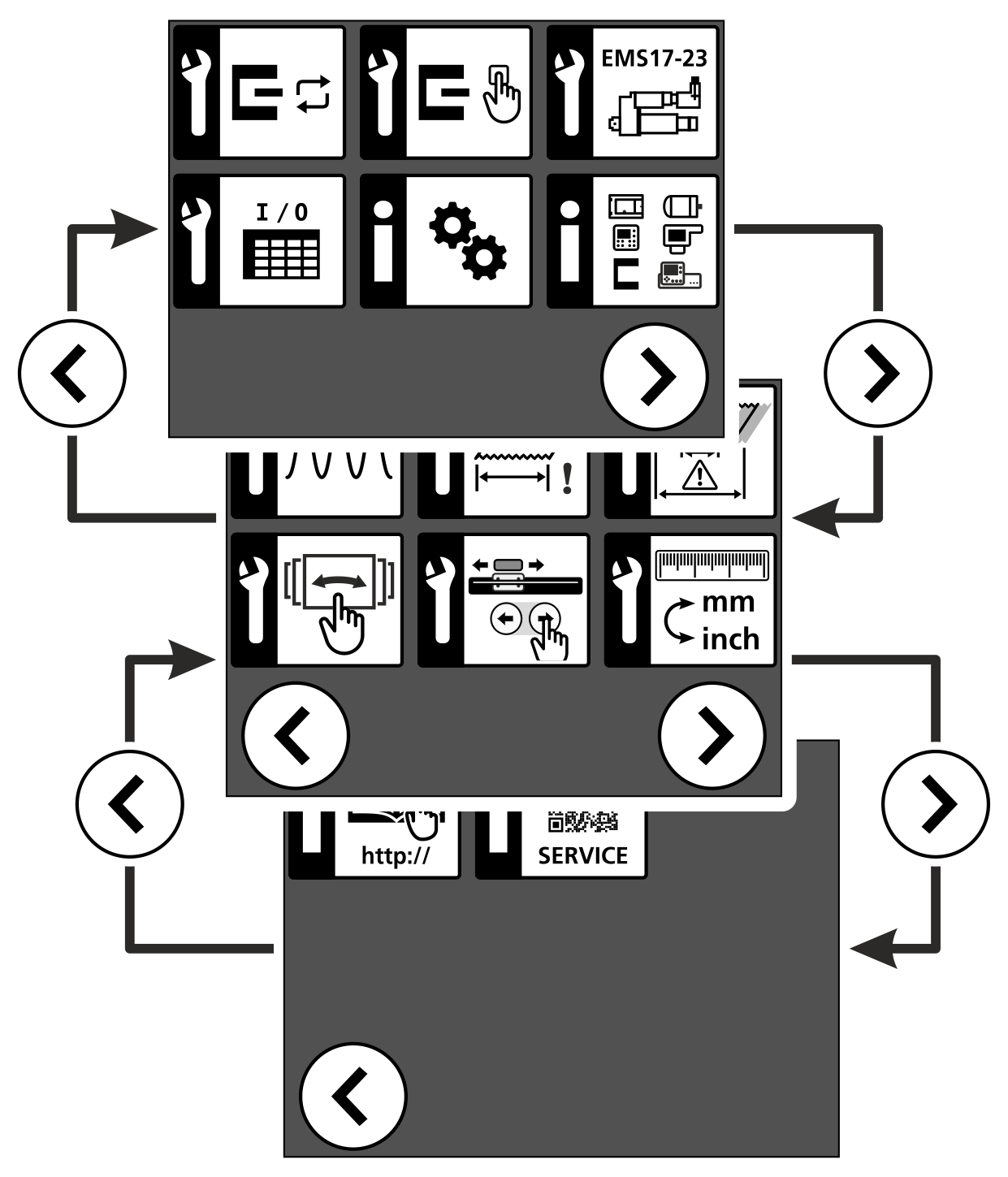
Calling up the setup menu

- The LED of the key illuminates.
- The controller switches to manual mode.

- The controller changes to setup mode.
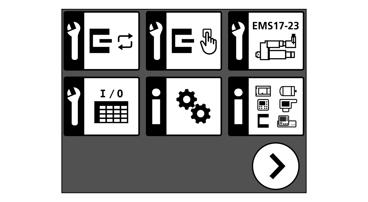

- Tap the symbol of the desired setting function or service display on the touchscreen.
- The setting menu or service display selected appears in the display.
The meaning of the different symbols is explained in the following table.
| Symbol | Component/Function | Setting/Display Function | Description |
|---|---|---|---|---|
Setting |
| Edge sensor | Performing the automatic material setup | See operating manual* |
| Performing the manual material setup | |||
| Selecting the IR 2011/40 edge sensor operating mode | |||
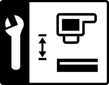
| Actuator with | Setting the stroke limitation and servo-center position | ||
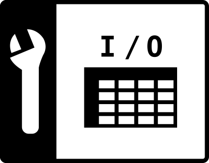
| Digital inputs / outputs | Selecting a function table | ||
| Oscillation | Defining the basic settings | See operating manual* | |
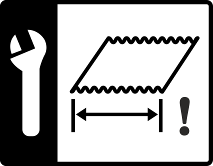
| Width measurement | Calibrating the width measurement | See operating manual* | |
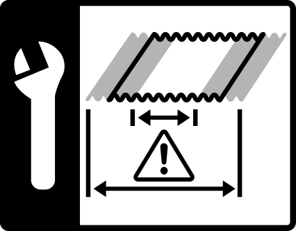
| Setting the warning and error limits | See operating manual* | ||
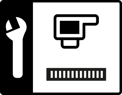
| CCD camera | Calibrating the CCD camera** | ||
| Carrying out the material thickness compensation** | |||
| Entering the position offsets | |||
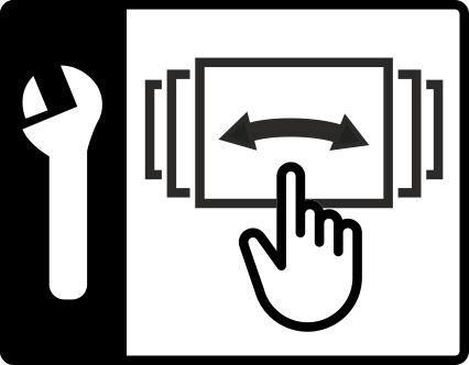
| Configurable displays and setting menus (swiping function) | Activating the displays and setting menus that can be displayed using the swiping function | See operating manual* | |
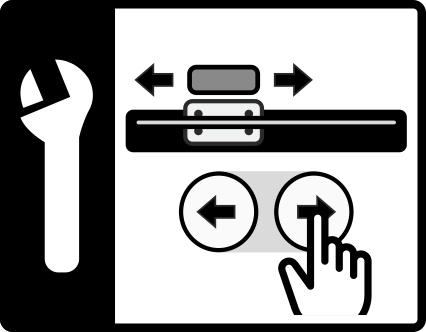
| Positioning unit | Commissioning the positioning unit for sensor 3 | ||
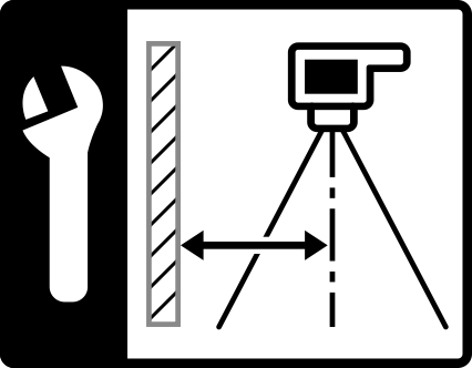
| Sensor positioner | Commissioning the sensor positioner | ||
| Dimension unit | Setting the dimension unit for the display and input of values (mm or inch) | ||
| ekr CON 600 net controller with integrated Profinet interface module | Defining the network settings of the Profinet interface module | See interface description ekr CON 600 net – Process data exchange via Profinet, document number MD.543. | |
| ekr CON 600 net controller with integrated Profibus interface module | Defining the network settings of the Profibus interface module | See interface description ekr CON 600 net – Process data exchange via Profibus, document number MD.555. | |
| ekr CON 600 net controller with integrated EtherCAT interface module | Defining the network settings of the EtherCAT interface module | See interface description ekr CON 600 net – Process data exchange via EtherCAT, document number MD.590. | |
| ekr CON 600 net controller with integrated POWERLINK interface module | Defining the network settings of the POWERLINK interface module | See interface description ekr CON 600 net – Process data exchange via POWERLINK, document number MD.610. | |
| ekr CON 600 net controller with integrated Ethernet interface | Defining the network settings of the Ethernet interface | See interface description ekr CON 600 net – Process data exchange via Ethernet, document number MD.566. | |
Service |
| Controller, | Showing the installed hardware, firmware and boot loader versions | See operating manual* |
| System components | Showing the system components connected | See operating manual* | |
| Link to the company website | Calling up the BST homepage | See operating manual* | |
| Service QR code | Showing service information and transmitting it to BST service | See operating manual* |













* Operating manual ekr CON 600, ekr CON 600 net, document number MD.542 ** Function is no longer available from firmware version 1.9.16 of the ekr commander control panel! |
